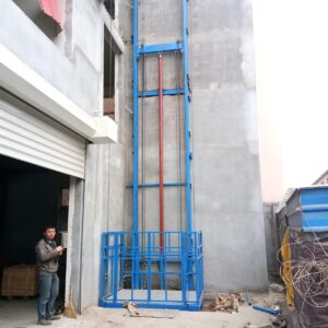
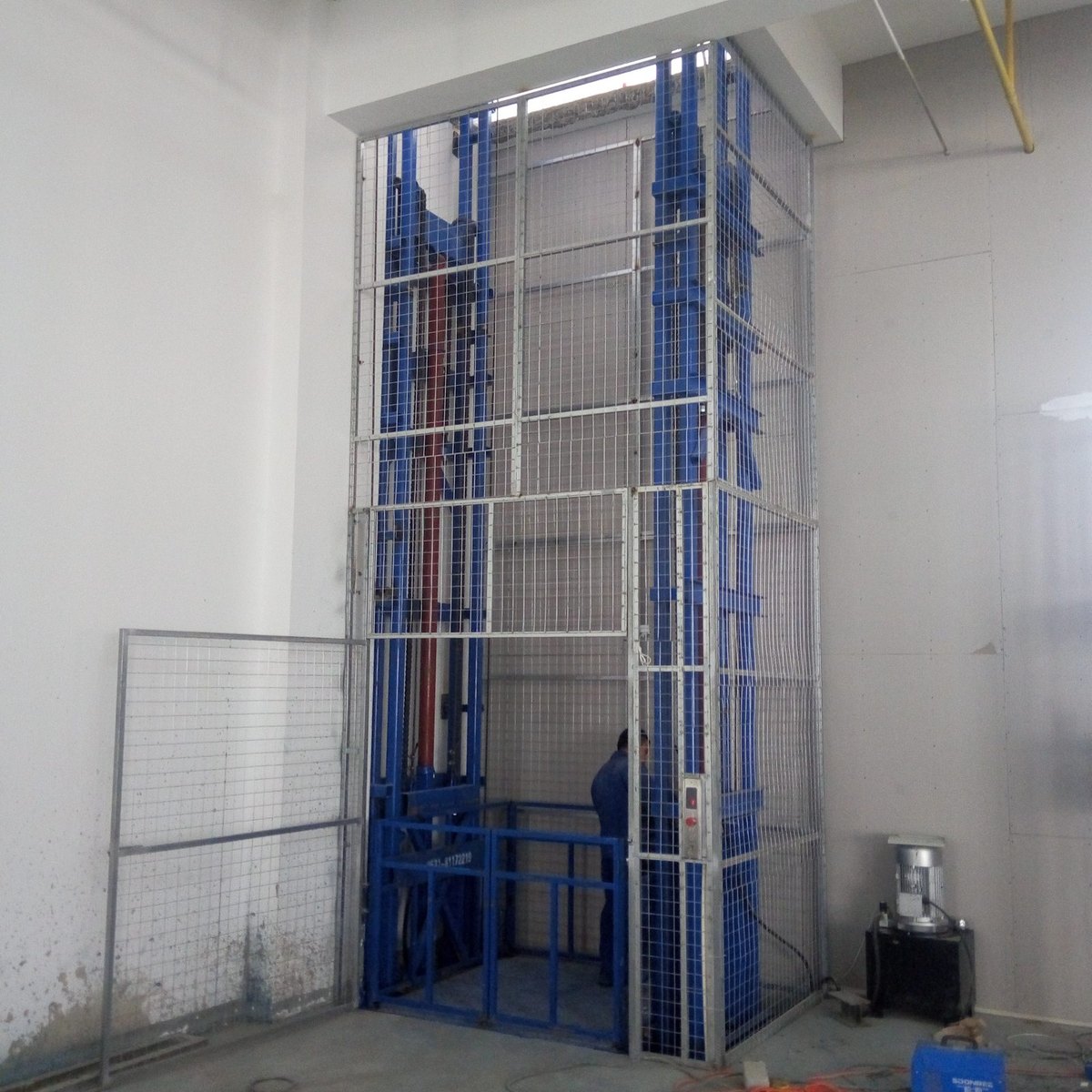
A shaft-free cargo lift does not remove the opening between floors; it changes how that opening is guarded. Instead of walls enclosing a lift car on every side, the platform travels between open landings. The platform guardrail protects people and goods while the platform is moving, while gates at each landing close the exposed floor edge when the platform is somewhere else. The two layers work together, and the interlock is what coordinates them.
Why does a shaft-free lift need landing gates?
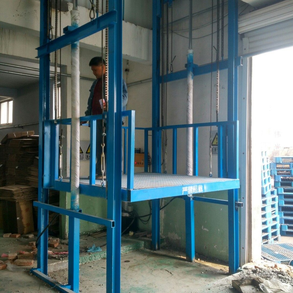
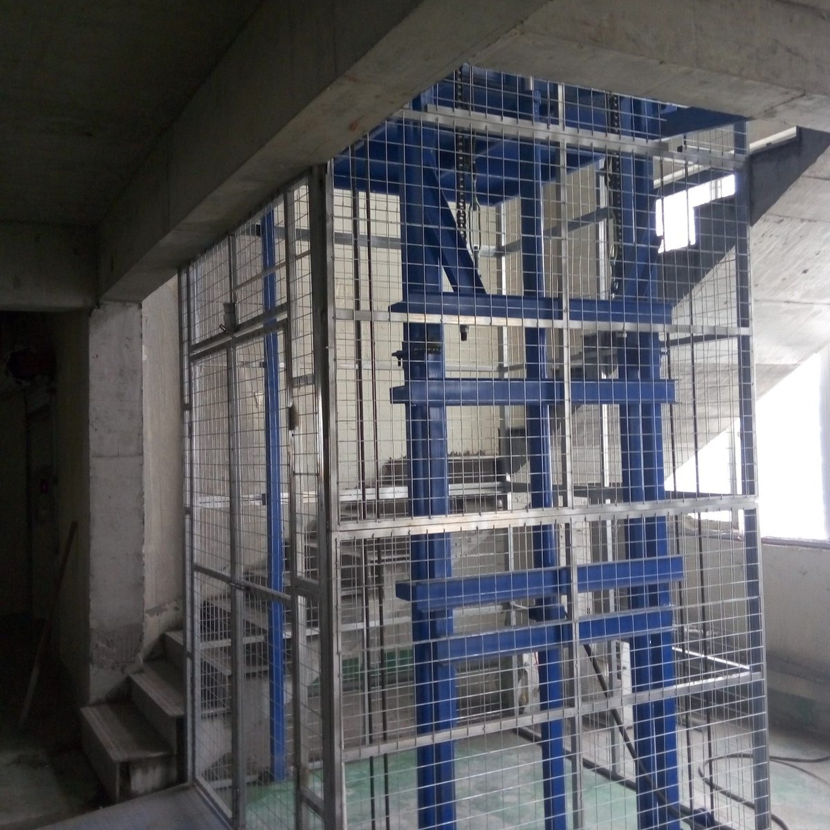
The upper floor contains a permanent opening through which the platform rises and lowers. When the platform is at another level, that opening is open to the mezzanine or floor below. A landing gate closes the edge at each level and prevents a person or trolley from walking into the open space. Our standard cargo lift uses interlocked landing gates on each level, so the gate is not treated as a loose piece of site fencing.
The platform has its own protection: 70 x 70 x 5 mm square pipe guardrails, 1000 mm high, around the moving deck. The landing gate and the platform guardrail are therefore doing different jobs. One guards the fixed building opening; the other guards the moving platform. Replacing one with the other leaves part of the lift cycle unprotected.
How does the landing gate sequence work?
The landing gate and the lift controls must act as one system. The operating rule is simple: the platform may serve a level only when the conditions at that landing are safe, and the gate remains under the control of the interlock rather than being opened independently. The PLC coordinates floor-by-floor operation at 24 V and receives the landing-gate status as part of the control sequence.
This sequencing matters most with through loading. A 180 degree layout has an entry side and an exit side rather than one enclosed car door. The operator moves goods across the platform without turning the load around, but the open edges at both ends make disciplined gate control essential. Before the lift moves, the route across the platform should be clear and the landing gates should be in the state required by the control system. The machine is designed to handle a load, not to compensate for an unsecured floor opening or a gate held open.
Landing gate or platform guardrail?
| Protection | Landing gate | Platform guardrail |
|---|---|---|
| What it guards | The fixed opening in the floor | The moving platform deck |
| Where it is fitted | At each landing | Around the platform |
| Main users | People and trolleys approaching the opening | People and goods travelling on the platform |
| Control link | Interlocked with the lift control sequence | Included in the platform structure |
| Does not replace | The platform guardrail | The landing gates |
What else protects the lift cycle?
The landing gates are one part of a wider safety arrangement. On the standard CL5-2.5 lift, two travel switches stop the platform at the upper and lower positions. The hydraulic circuit includes an explosion-proof valve on the hydraulic pipe, a relief valve for overload protection and an emergency descent valve for lowering when power is unavailable. The information we publish describes the equipment functions; installation and operation should still follow the approved layout and the manual supplied with the machine.
Pre-use inspection should concentrate on things a control system cannot see. Check that each gate moves cleanly, that the floor edge and gate frame are secure, that the interlock indicators and controls respond as described in the manual, and that the platform path is free of loose material. Look at the platform guardrail and the anti-skid deck as well. A damaged gate or a bent guardrail should be taken out of service and examined before the next lift.
What changes on a multi-level installation?
A two-level lift has one upper opening and two landings. Each additional level adds another fixed opening and another landing gate, so the protection has to be designed as a complete set rather than copied from the top level alone. A three-level project in Ningbo used a 1.3 x 1.3 m through-loading platform and additional protection mesh around the landing openings. The smaller footprint did not change the principle: people at every level need a protected edge, and the control sequence must account for every landing.
For the two-level warehouse project in Bosnia, the specification combined a 2.5 t capacity, 5 m of travel, a 1600 x 2200 mm platform, 180 degree through loading and interlocked landing gates. The full arrangement was shown on the general arrangement drawing. That drawing is where gate swing, floor-edge fixing and the relationship between the gate and the platform path can be checked together before installation.
What should the installation drawing show?
A useful drawing should identify the clear opening at every level, the gate position and opening direction, the fixed frame or wall to which the gate and rails connect, and the space needed for a trolley to enter and leave. It should also show the platform at the upper and lower stops, because a gate that fits the platform parked at one level may not clear it during travel. Review the drawing before the floor edge is finished; corrections are much easier before anchors and finishes are in place.
The gate should not become a substitute for housekeeping. Bins, pallets and packaging left against a landing can obstruct the gate or the approach, while goods stacked above the guardrail create a separate risk. Keep both sides of a through-loading lift clear, and keep the landing edge visible. The interlock can control the lift, but it cannot keep a walkway clear.
Frequently asked questions
Can the platform move while a landing gate is open?
The landing gates are interlocked as part of the lift control system. The intended control sequence is that the platform does not travel with a landing gate in an unsafe state. If a gate or its interlock is damaged or behaves abnormally, stop using the lift and arrange inspection rather than attempting to bypass it.
Does a through-loading platform need gates on both sides?
A 180 degree through-loading layout exposes two sides of the platform route. The fixed openings at each floor still need to be guarded, so the landing layout and gate arrangement should be shown on the approved drawing for the complete installation rather than decided from the platform alone.
Are landing gates enough without a shaft?
No single device protects the whole lift cycle. The landing gates protect the fixed floor openings, the 1000 mm platform guardrail protects the moving deck, and the hydraulic and travel controls manage other machine functions. Use them as one coordinated system and follow the manual and approved layout.
Next step
Send photographs of every landing, the clear opening, the floor-edge construction and the trolley route, and we can check the gate arrangement against the lift layout. Start from the cargo lift range or the double guide rail cargo lift, and use our guide to measuring a mezzanine for a cargo lift before the site survey.